Eldon Deardorf
a Tribute by Lawrence K. Smiley
July 29, 2019
My business partner, mentor, encourager; and the best friend one could ever have!
I met Eldon while he was working as a mechanical engineer for Butler Engineering – an engineering subcontractor to Delco Electronics (Delphi) in Kokomo, IN. As a molded rubber manufacturer’s representative selling rubber switch pads, I worked on many HVAC and Steering Wheel projects with Eldon.
One would have never guess that beneath this soft-spoken, gentleman of a gentleman’s exterior, was a courageous navigator who flew 103 missions in jet fighters during the Vietnam War. A Lt. Colonel in the Air Force, Eldon was true hero, who placed himself in harm’s way 103 times to serve his country.
Following his retirement from Butler Engineering, he agreed to work for me and SMS Technologies, a division of SMS Marketing, Inc., helping develop a new type of turbine engine. His creativeness (Holder of 3 US Patents) complimented, well, his creative mind, determination and work ethic to not only find solutions, but also to bring them to life, as functional mechanisms. We turned the attic over his garage into a working laboratory, where we built a working, instrumented, turbine prototype when injected with room temperature, pressurized air.
However, we were limited by the low working temperatures of existing materials of construction. As a result, the project was placed on hold, until a new, high temperature (2600°F) material was developed that could be, successfully, manufactured.
At that point, my largest customer, Delphi, went bankrupt, which put SMS Marketing, Inc. out of business. As a result, I had no funds to pay Eldon for his efforts. We, mutually, agreed to bring another product (ladder related) to market, as business partners. Eldon and I engineered this product and built a prototype. After setting up a production line and building and boxing 100 ladder platforms, manufacturing liability insurance premiums stopped us cold. We couldn’t, profitably produce enough platforms to pay the huge premiums; so that project also hit a brick wall.
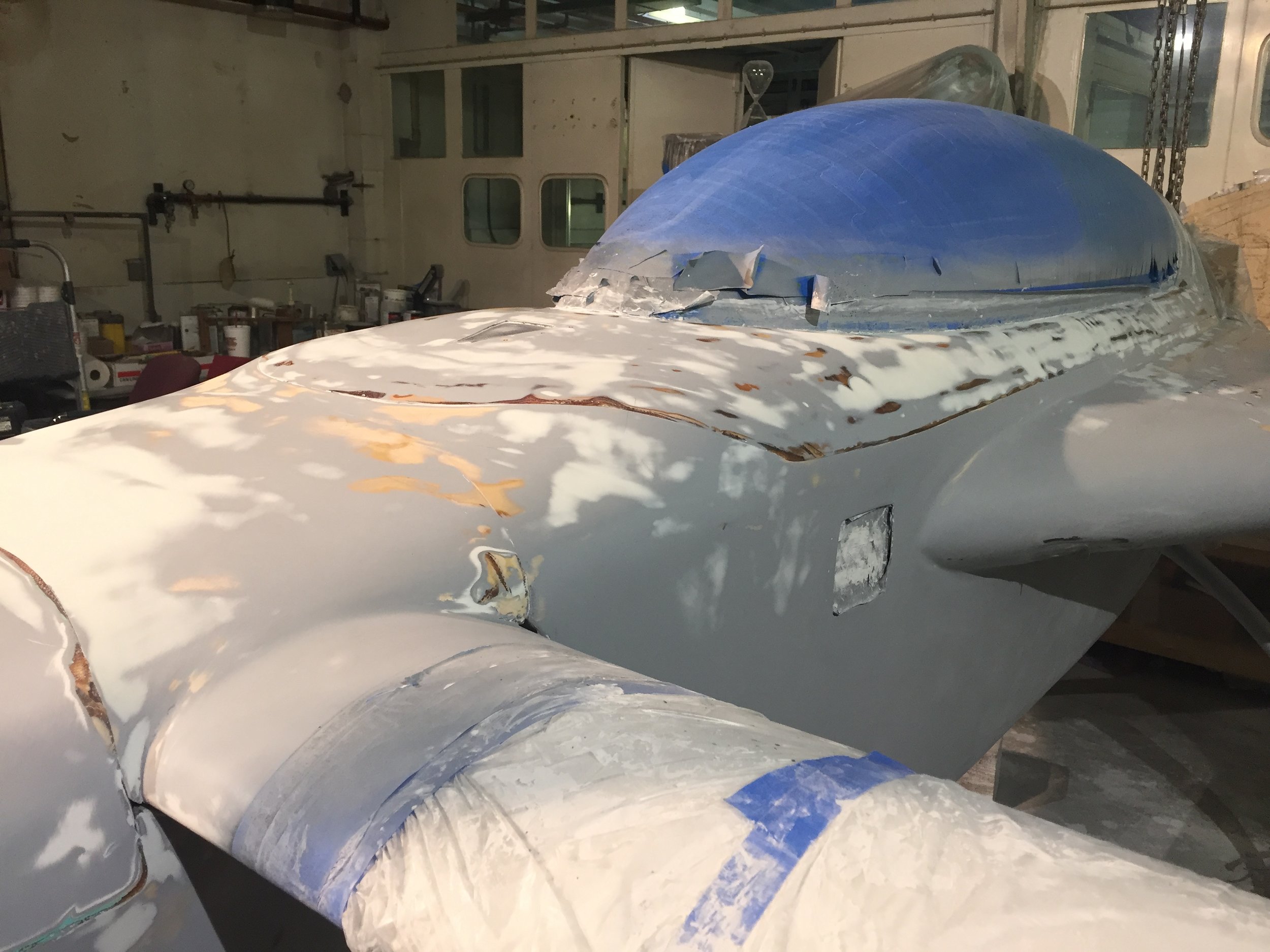
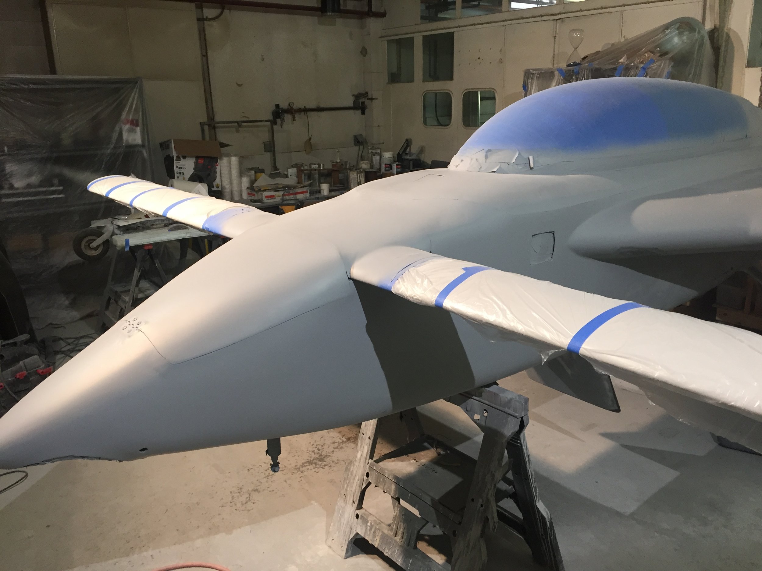
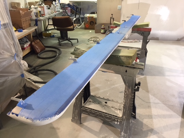
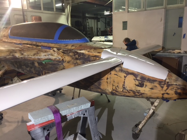
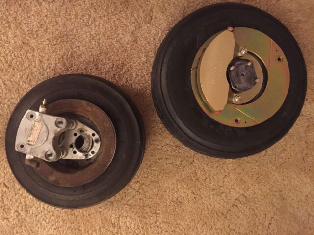
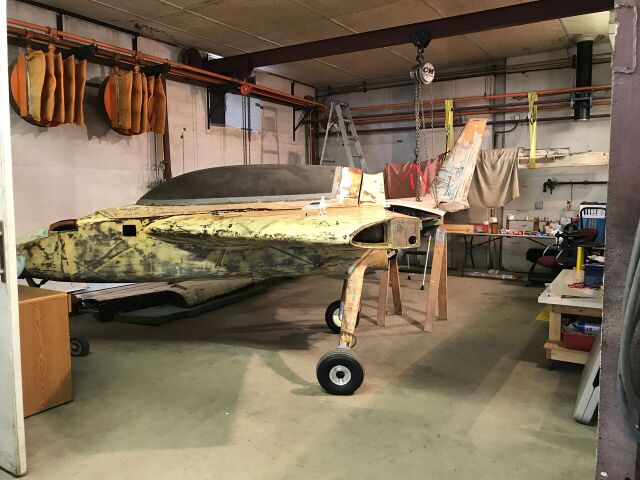
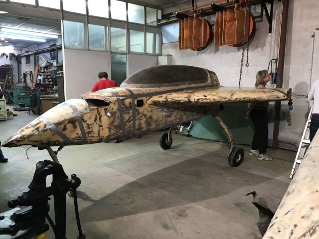
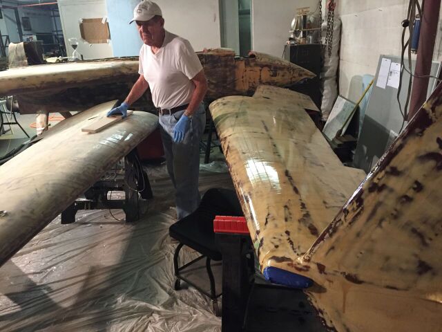
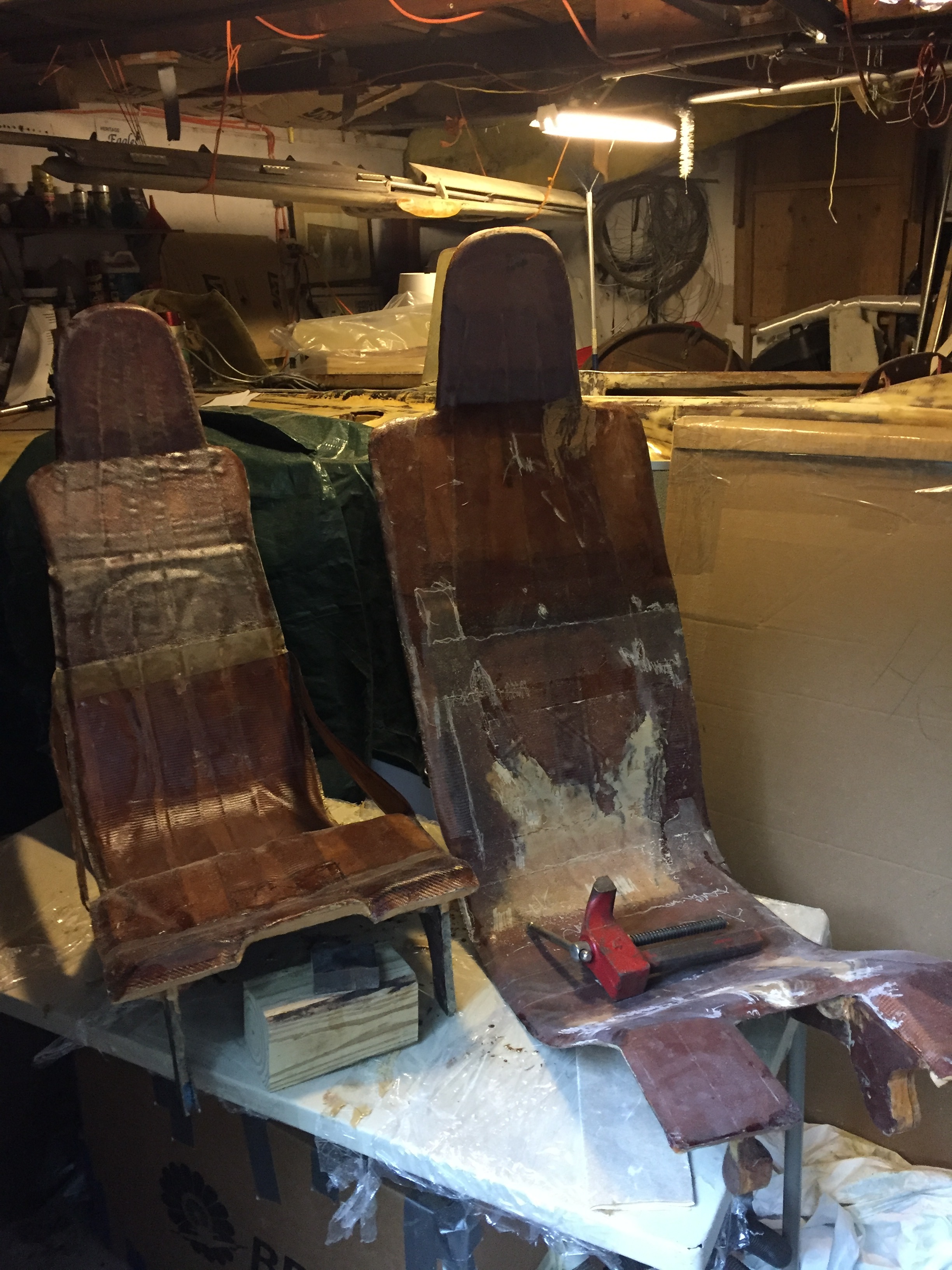
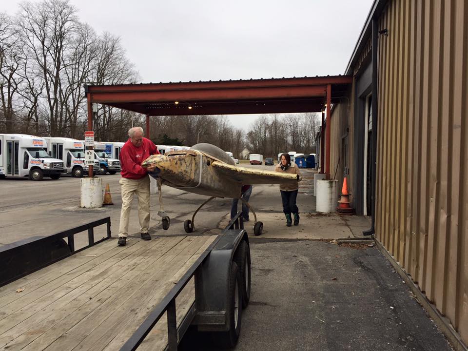
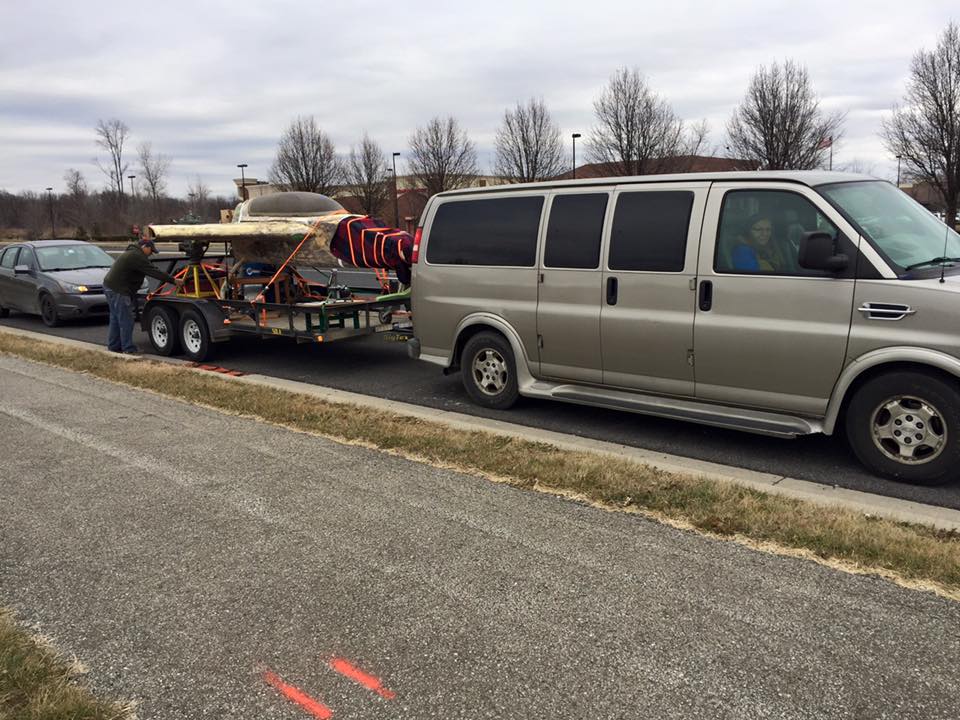
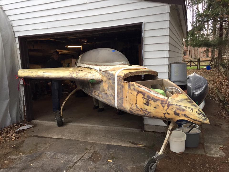
At that point in time, I came to the conclusion that another, smaller, project (building my 70% completed home-built airplane, LongEZ N724DT) had to be completed before I would have success building a high temperature turbine engine. So, Eldon, once again, came along side of me to help finish N724DT. And, that is another factor that makes his untimely death SO sad. He will never get to ride in the plane in which he invested SO many hours working, together, with me.
Even though we never discussed this, Eldon was, sort of, a second father to me. I depended upon him in many ways. One could not find a better friend, business partner and a fellow engineer. He taught me to be more compassionate by suggesting that we use JANUS’ workers, many with Down Syndrome, as our workforce. He taught me persistence, by diligently working though any problems and successfully bringing to life his creations. I will miss him very, VERY much.
However, I do know that he knew Jesus and believed that Jesus, the Messiah, was God’s son. As I told him the day before he departed his body and ‘flew’ through the light-lined tunnel from this earthly existence to his heavenly home, “Eldon, in heaven time disappears, so if you die you will find yourself in heaven, where it will seem, to you, that we will be right there with you in the blink of your eye.”
I, truly, thought Eldon would survive for another 10 years, or so; and that is what we were all praying for. However, the good Lord had another outcome planned. Eldon is, now, enjoying paradise, after leaving his weakened body. It is we, who are left behind that grieve, deeply, his passing. Lord, please help us all find comfort; and, yes, even joy; as time heals us of our great loss.


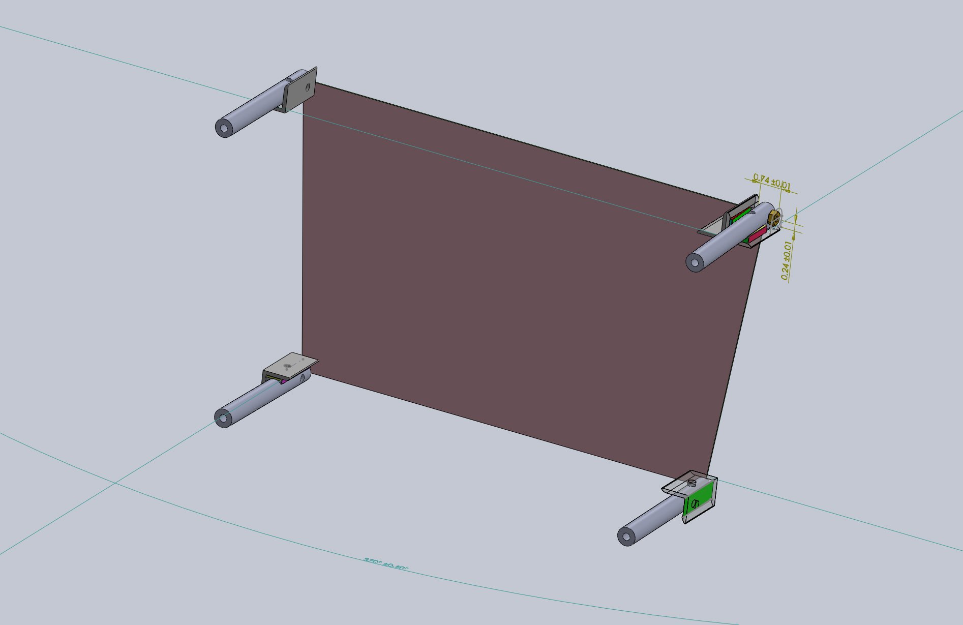

![Shim_Bottom Port [LKS-0021-Rev 3]](https://images.squarespace-cdn.com/content/v1/5727779337013b4a807d315a/1656293352908-XEUW5QW0N9OZ2YXMI7KV/%5BLKS-0021-Rev+3%5D+Engine+Mt.+Bottom+Port+Shim.JPG)
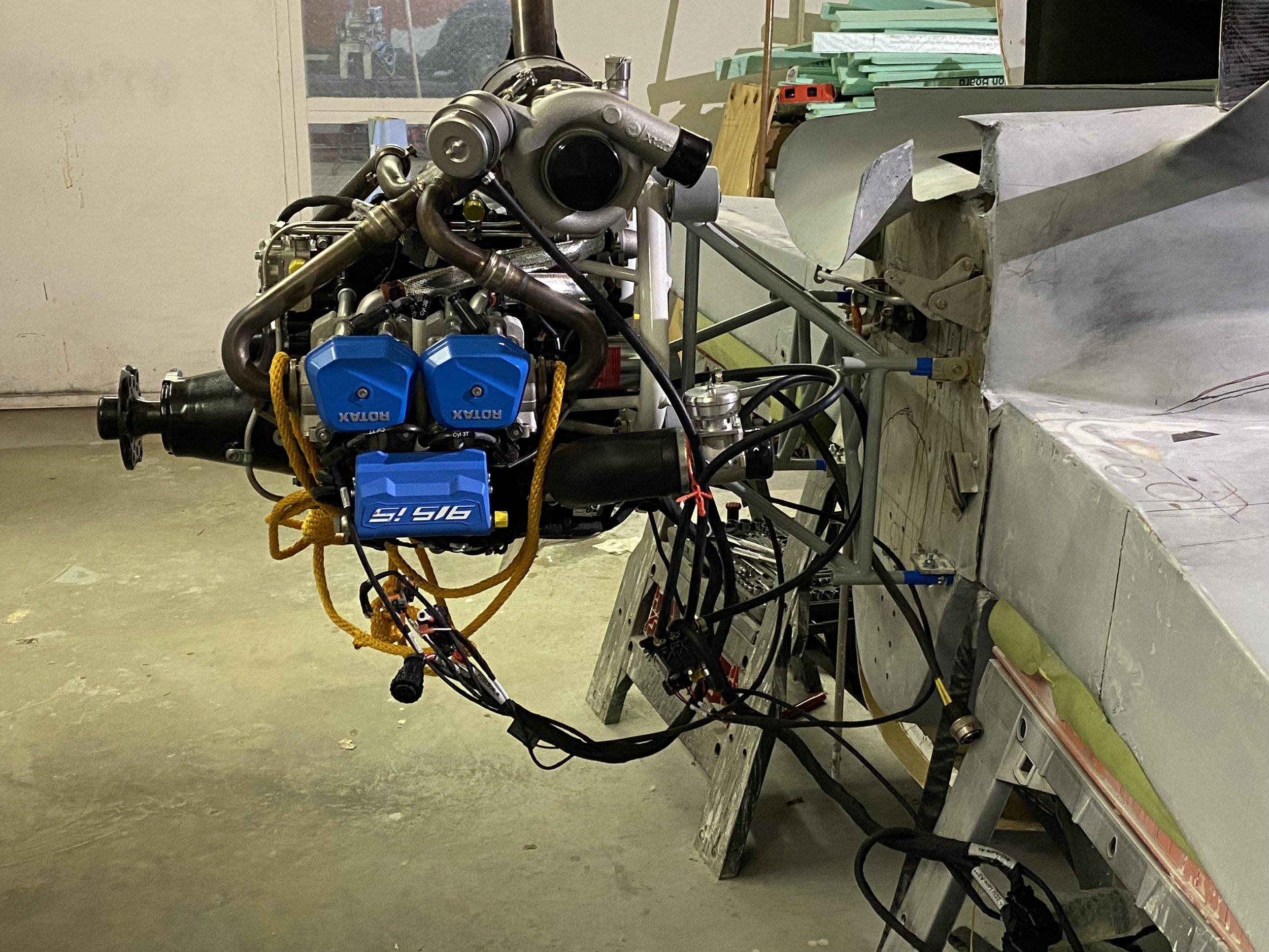
![Engine Mount [LKS-0001-Rev 9]](https://images.squarespace-cdn.com/content/v1/5727779337013b4a807d315a/1656424748903-JTS7O0XMMWAZDIE04DIJ/%5BLKS-0001-Rev+9%5D+New+Engine+Mount_Rear+View.JPG)


![[LKS-M2006] MOLD IC Diffuser .JPG](https://images.squarespace-cdn.com/content/v1/5727779337013b4a807d315a/1617740546861-NM3VZCH846YIXCNQ03XG/%5BLKS-M2006%5D+MOLD+IC+Diffuser+.JPG)