
It has been over a year since I updated this blog. When I purchased a ROTAX 915 iS and an MT Variable Pitch Propeller, I transformed myself from an aircraft builder to an aircraft developer from the firewall back to the pusher propeller.
In other words instead of following a ‘cookbook’, I’m creating the ‘cookbook’.
That decision slowed my homebuilding progress, exponentially. However, the resulting design process has ignited my need to learn SolidWorks CAD. Slow at first, I’m getting the hang of it. Furthermore, using a computer, instead of a drafting board, has proven beneficial in more ways than I can count.
Now that I’ve received my redesigned engine mount, designed my fuel system and fabricated cowl jigs (see below), I’m ready to fabricate the bottom cowl. I’m also starting to see a light at the end of my 45-year-long aircraft building tunnel! Thanks for everyone’s encouragement. It means a lot to me!!!
The large majority of my time over the past year has been consumed by:
Fabricating a new Engine Mount, working with Aerospace Welding, Inc, to tweak the finished engine mount, as close as possible to my LongEZ Firewall’s Four (4) attach points. After which, Three (3) Shims were required to fill all remaining gaps.


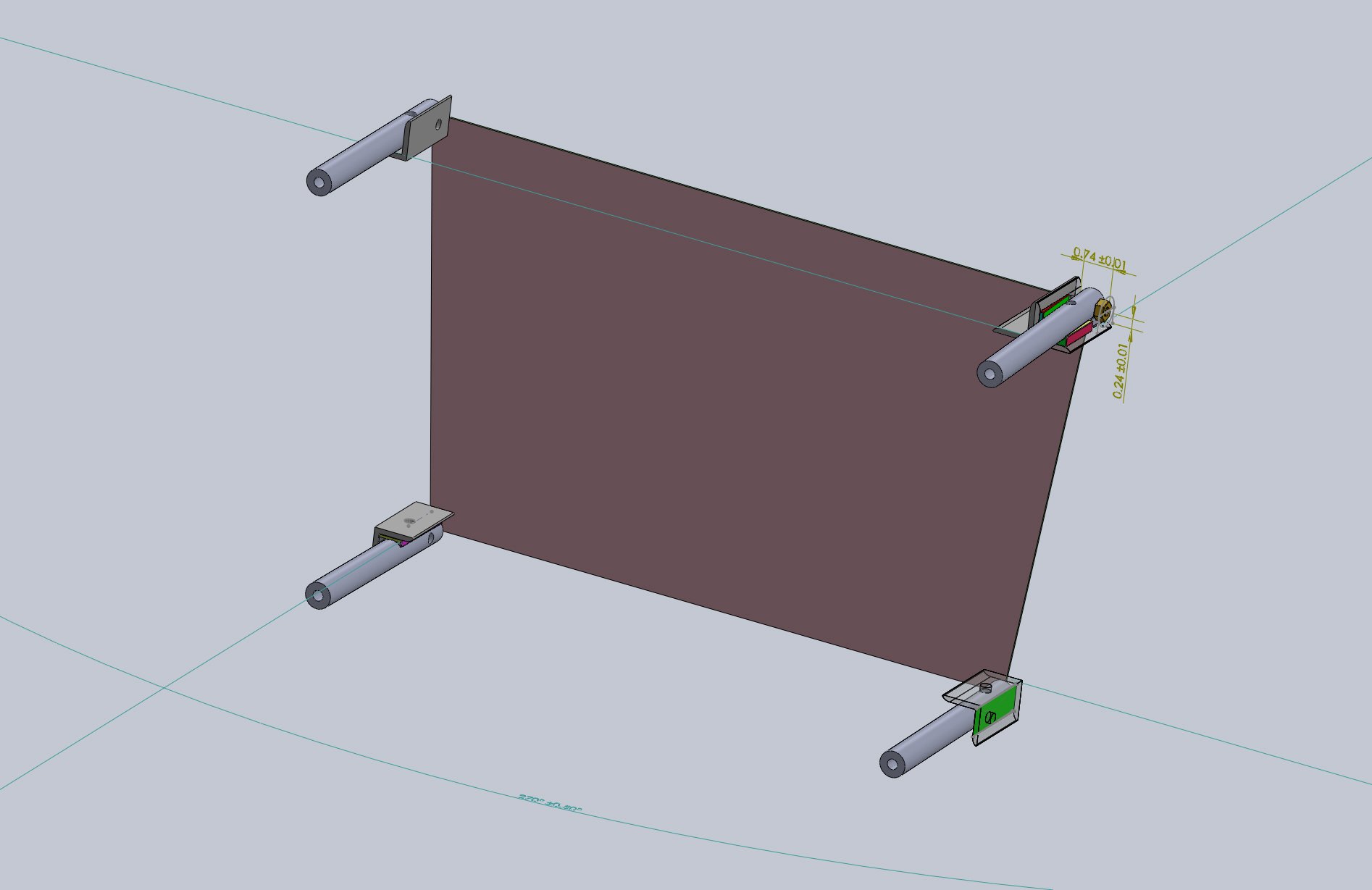

![Shim_Bottom Port [LKS-0021-Rev 3]](https://images.squarespace-cdn.com/content/v1/5727779337013b4a807d315a/1656293352908-XEUW5QW0N9OZ2YXMI7KV/%5BLKS-0021-Rev+3%5D+Engine+Mt.+Bottom+Port+Shim.JPG)
![Engine Mount [LKS-0001-Rev 9]](https://images.squarespace-cdn.com/content/v1/5727779337013b4a807d315a/1656424748903-JTS7O0XMMWAZDIE04DIJ/%5BLKS-0001-Rev+9%5D+New+Engine+Mount_Rear+View.JPG)
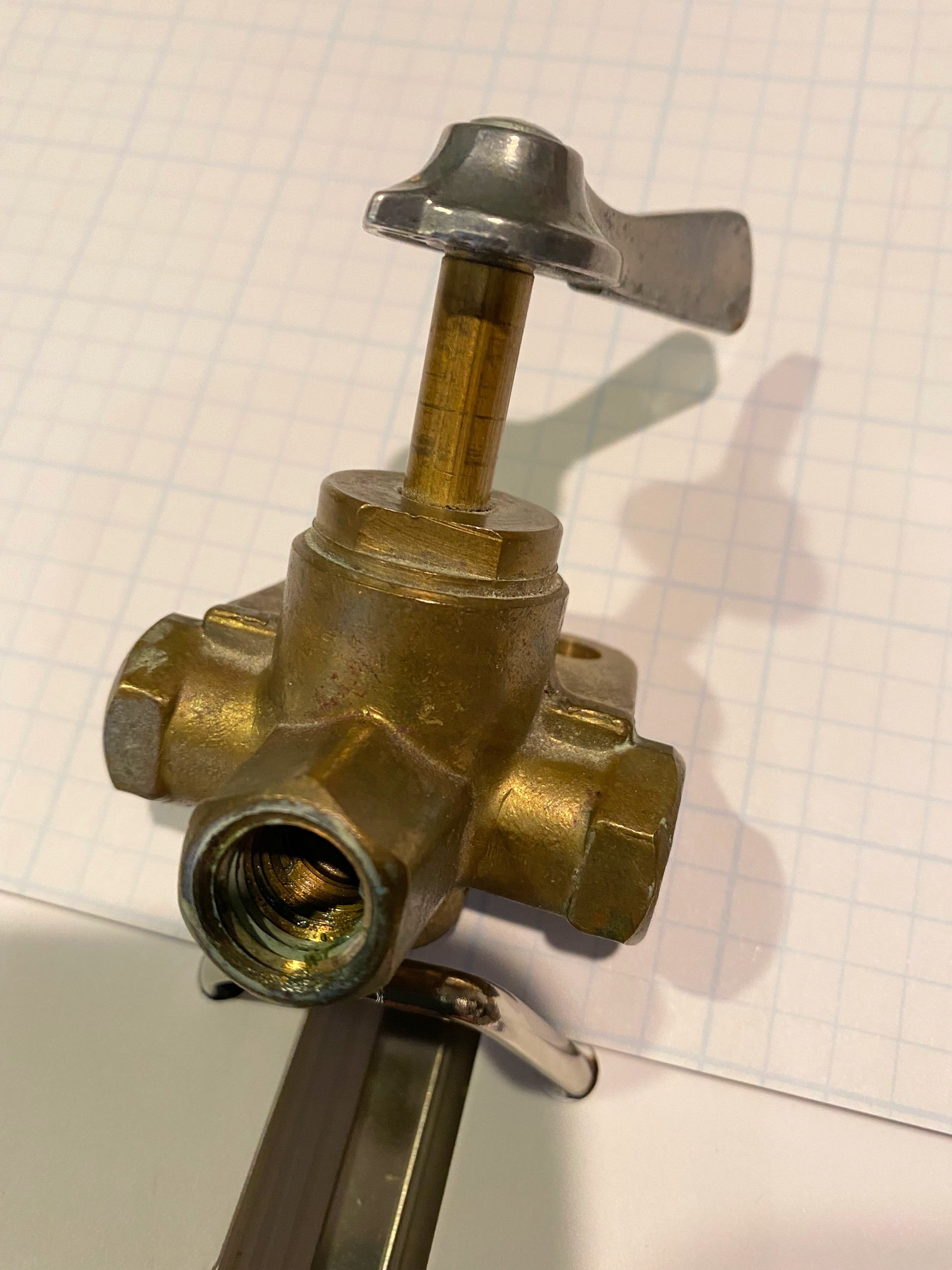
2. Changing from a Carbureted Engine to a Fuel Injected Engine required replacing an old 3-Way Fuel Selector Valve with a new 6-Way Fuel Selector Valve; and adding three (3) new fuel lines (yellow in diagram below).
The new Fuel Injection System directs fuel more bypass fuel (OVERFLOW) to EACH tank via the new Fuel Selector Valve. The upgraded system prevents overfilling one tank and dumping fuel overboard, as the engine runs.
This required drilling through the inside starboard wall of the fuselage into the starboard fuel tank, inserting a new fuel line that connected to the new Selector Valve located at the front of the cockpit; adding a new overflow fuel line from the engine to the new Selector Valve; and splicing a new fuel line to the existing port tank overflow line.
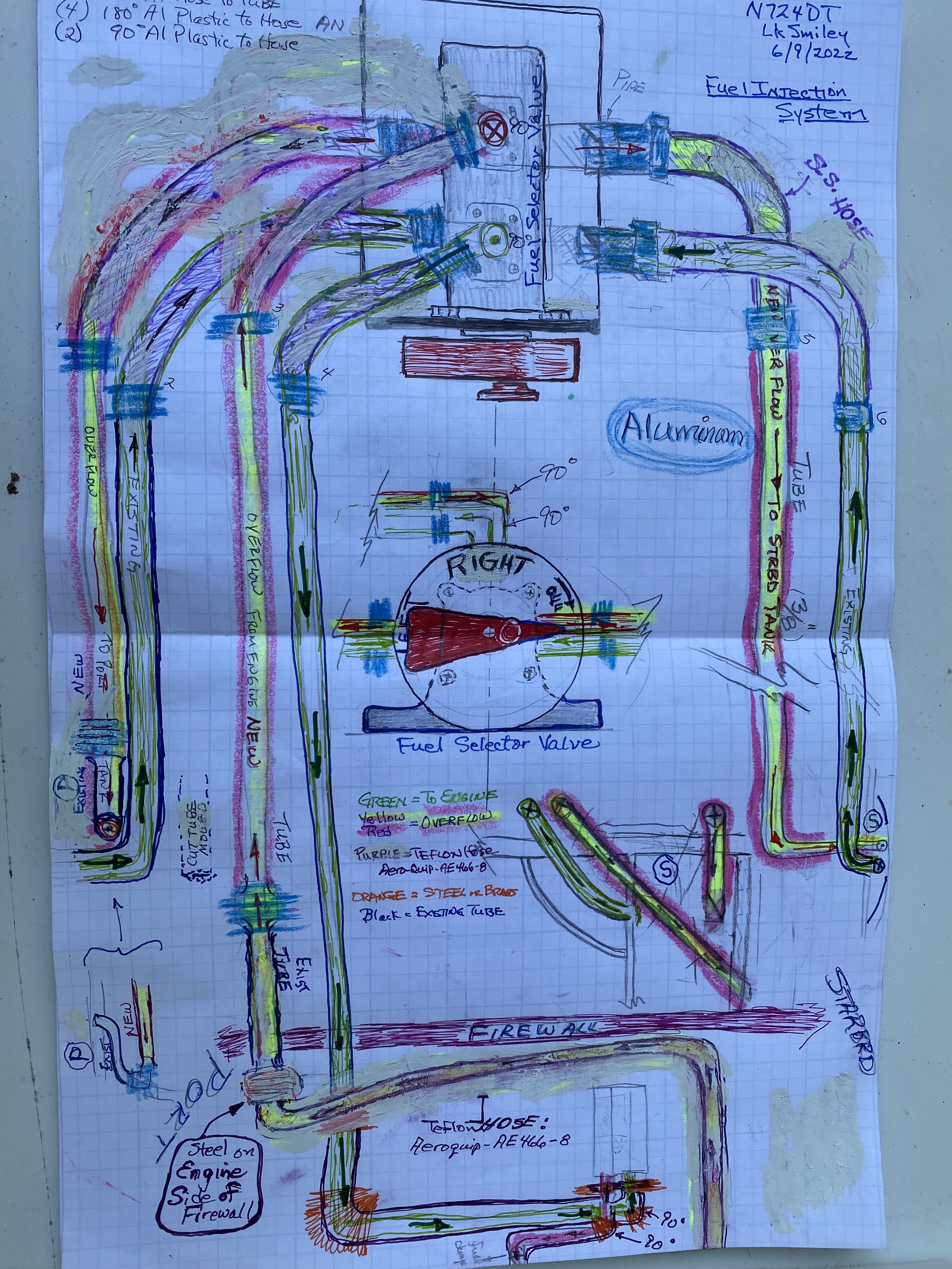
FUEL INJECTION SYSTEM DIAGRAM

3. Designing & Fabricating the MDF JIGS required for COWL Fabrication. SolidWorks files were converted to .dxf files that were fed into a computer controlled router.

MDF COWL CAP & COWL CAP FRAME
Routing Cowl Cap Frame
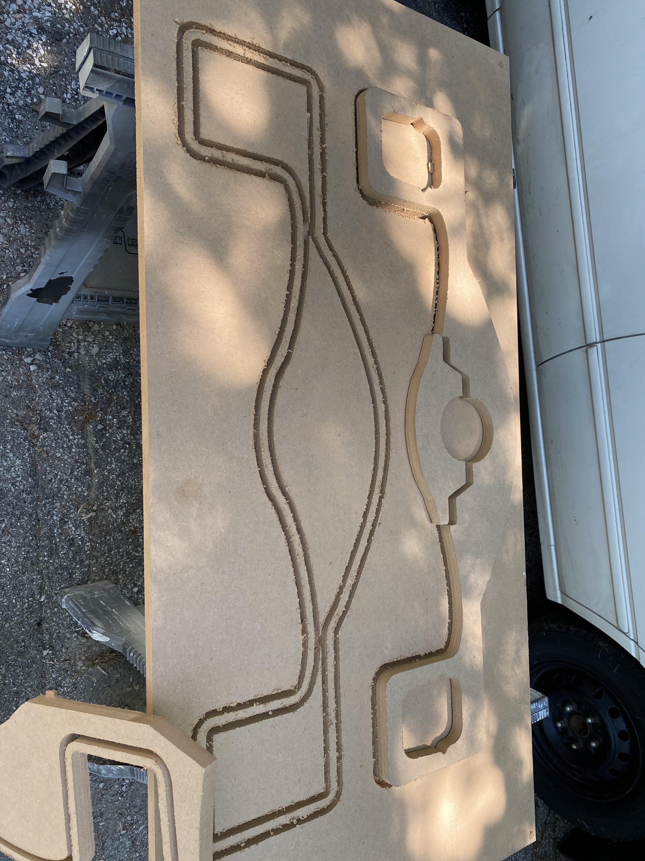
MDF Cowl Jig Frame & End Cap

MDF End Cap & Frames Assembled on Nozzle